| Buyer concern | What we review |
| Datum and hole position | Review mounting faces, datums, hole location, threads, and relationship to mating parts. |
| Pockets and tool access | Check corner radii, depth, wall thickness, access direction, and surfaces that need machining. |
| Thin walls and flatness | Identify deformation-sensitive areas and the surfaces that decide fit or sealing. |
| Finishing and assembly | Confirm finish, edge break, masking, cosmetic zones, and inspection priorities. |
Progressive stamping is driven by a connected set of decisions: strip material, feature sequence, die layout, finished-part condition and expected production demand. Send the current drawing and, where available, a 3D model. Identify material grade and thickness, annual or order volume, critical dimensions, bend or form requirements, surface condition, and whether the part must remain attached to a carrier during intermediate operations. If you already own tooling, provide its drawing, condition record, trial samples and transfer expectations. Those inputs make it possible to separate a usable production route from an early concept.
| RFQ input | What to provide | Decision it supports |
| Part definition | Current 2D drawing, CAD, sample, revision and any mating-part information. | Station sequence and feature feasibility. |
| Strip material | Material grade, thickness, temper or coating requirement, preferred coil form if known. | Formability, burr direction, springback and material sourcing discussion. |
| Program demand | Initial quantity, annual forecast, repeat-order expectation and program stage. | Whether dedicated progressive tooling is appropriate for the business case. |
| Critical requirements | Tolerances, hole position, formed profile, flatness, cosmetic side, edge condition and inspection needs. | Die design priorities and an acceptance route that reflects function. |
| Tooling status | New tooling request, existing die information, ownership expectation and sample approval requirement. | Tooling scope, try-out plan and responsibility boundaries. |
Specify the functional side, edge condition and downstream contact requirement instead of treating burr as an afterthought.
A small drawing change can alter pitch, carrier, station count or die features, so release status matters before tooling moves.
| Characteristic | Project reference | Confirmation needed |
| Material form | Coil or strip material selected for the part function and forming route. | Grade, thickness, temper, coating and available supply form. |
| Feature sequence | Piercing, blanking, bending, forming or coining arranged by die station as applicable. | Part geometry, carrier logic, access and tooling concept. |
| Dimensional control | Critical features defined from drawing datums and functional interfaces. | Material behavior, formed condition, measurement method and acceptance criteria. |
| Burr direction | Identified where it affects contact, assembly, safety or cosmetic appearance. | Cutting direction, secondary operation and final-use surface. |
| Tooling release | Try-out and sample acceptance route agreed for the individual project. | Tooling status, revision, required evidence and change-control responsibility. |
| Material | When It Is Commonly Considered |
| Aluminum | Lightweight shafts, spacers, housings, collars, and non-heavy-wear assemblies |
| Stainless Steel | Corrosion-resistant fittings, shafts, pins, sleeves, and exposed mechanical interfaces |
| Carbon and Alloy Steel | High-strength shafts, pins, drive components, and wear-related mechanical parts |
| Brass and Bronze | Bushings, fittings, connectors, low-friction interfaces, and corrosion-sensitive components |
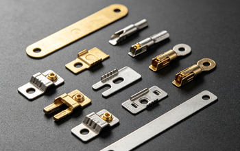
For terminals, contacts, tabs and shields, the key question is often the condition of the working interface. Material, plating, burr direction, formed clearance and packaging orientation can influence how the part reaches a later assembly step. Describe the contact zone and mating condition in the RFQ. That lets the tooling and finishing discussion follow the part’s actual connection function rather than a generic stamped-part description.
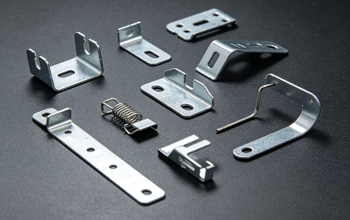
For brackets, clips and retaining features, a drawing should show more than the flat blank. It should identify the formed position, locating surfaces, assembly direction, load-relevant features and any visible side. This matters because a progressive die may combine piercing and forming at different stations. The technical review then focuses on the relationship between the final formed profile and the part it must mount, guide or retain.
A progressive route is most useful when the part definition is sufficiently stable for a dedicated tool strategy. When a program is still changing, separate the design-validation question from the repeat-production question. You can then identify which revisions affect strip pitch, carrier support, station layout or downstream operations before they are embedded in tooling. This makes the tooling decision part of purchasing control, not a hidden cost after launch.
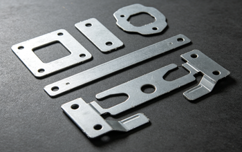
Progressive die stamping moves coil or strip material through a die with multiple stations. Each station performs a related operation, such as piercing, blanking, bending, forming or coining, while the part remains supported by the strip until a later release stage. It is a process choice for repeat parts whose geometry and demand support a dedicated station sequence, rather than a universal substitute for all metal stamping.
Progressive stamping is commonly evaluated when carrier-strip support can remain useful while the part advances through several operations. Transfer stamping may be considered when the part needs to leave the strip early or requires greater freedom between forming operations. The correct route depends on geometry, draw depth, handling, material flow, projected demand and tool concept. Review the drawing before deciding from the process name alone.
Tooling cost depends on the part geometry, number and type of stations, material behavior, critical features, expected die life, sensing or handling requirements, trial plan and change-control needs. A meaningful quotation should distinguish tooling scope from part price and clarify what happens if the design changes. Give the annual demand and program stage so the tool strategy can be judged against the intended purchasing life of the part.
Provide the current drawing, revision, material grade and thickness, annual or order quantity, critical dimensions, formed requirements, cosmetic side, finish, inspection needs and packing instructions. Add mating information when the part connects, retains or carries current. If you have existing tooling, provide tooling drawings, samples, current condition and ownership information. These inputs allow a review of both the part and the program, not just a single unit price.
Yes. A change to a hole, bend, profile, pitch, material thickness, coating, tolerance or mating interface can affect carrier support, station sequence, die features or inspection requirements. Identify the revision clearly and explain the functional reason for the change. This lets the engineering discussion decide whether the modification is local, whether a new try-out is needed, and how the updated part definition should be released.